
matosicv0.0.0.10
2026-05-21
The first key fired.
Parts arrived in waves. I hadn't soldered in ten years. A friend taught me continuity. The fresh XIAO worked, the soldered one didn't, and then I went back and re-read my own schematic.
Parts arrived in waves
The Kailh hot-swap sockets and the Cherry MX switches for the macropad showed up before the XIAO RP2040 did. So while I waited for the microcontroller, I started practising on the through-hole parts. I had some solder left over from a project years ago.
It had been about ten years since I last held a soldering iron — university electronics lab, vague memories. I watched a few YouTube videos to remind myself what a clean joint actually looks like, then started on the Kailh sockets.
They came out looking okay to me, but I had no way of telling whether they actually worked. A friend who's done this stuff for years walked me through how to check — touch the probes to the right pads with the meter on continuity (beep) mode, press the switch when it's seated, listen for the beep. He also showed me to use less solder than I was using, and to keep the iron on the pad longer than felt comfortable so the joint actually wets.
I worked through the nine sockets and the four expansion headers. None of it was beautiful but all of it checked out on the meter. (The EC11 rotary encoder hasn't shipped yet — that's in a later parts batch, and bring-up of the encoder is a separate post when it arrives.)
Then the XIAO arrived
I flush-mounted it onto the board using its castellated edge pads. About five of the fourteen joints weren't properly making contact — you could see the solder hadn't actually wet to the pad. Added more flux, re-touched each one with the iron on for longer, checked continuity from every XIAO pad through to wherever it was supposed to go on the PCB. Eventually all fourteen passed.
Plugged the USB-C in. CIRCUITPY drive mounted. CircuitPython
10.2.1 was already on the module from a previous hobby project.
I copied a minimal firmware across — configure every GPIO as a pull-up input, print which one goes low when a switch is pressed:
import time, board, digitalio
pins = [getattr(board, f"D{i}") for i in range(11)]
dios = []
for p in pins:
    d = digitalio.DigitalInOut(p)
    d.switch_to_input(pull=digitalio.Pull.UP)
    dios.append(d)

while True:
    for i, d in enumerate(dios):
        if not d.value:
            print("D{} pressed".format(i))
    time.sleep(0.01)
Mashed every key on the board. screen attached to the USB
serial port saw nothing. Pressed buttons a lot more times. Still nothing.
I left it on the desk and walked away. Came back a day later, tried again, same nothing. Walked away again.
Wednesday, one more hour
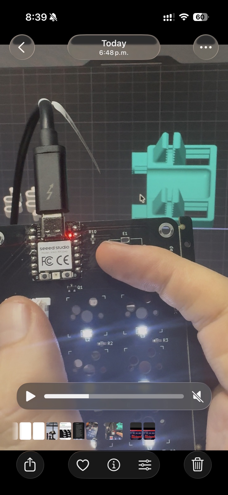
Came back Wednesday May 20th evening for one more attempt. This time I started with a basic diagnostic: pulled the soldered XIAO out of the macropad's socket, grabbed a brand-new unsoldered XIAO RP2040, plugged that one directly into USB. Loaded a stock NEOPIXEL demo. The built-in RGB LED on the fresh module cycled through colors.
So my CircuitPython workflow was fine. My USB cable was fine. The XIAO module itself, as a piece of hardware, was fine. That left two suspects: the macropad PCB, or my firmware.
I went back to my schematic to look at the first one. That's where I noticed what I'd been missing.
What I'd been missing
The nine switches on this PCB are not nine independent buttons each on their own pin. They are a 3×3 matrix with anti-ghosting diodes (D1–D9). To detect a press in a matrix, you drive one row LOW at a time and read the three columns; a pressed key in that row pulls its column LOW through the diode. With every pin sitting as a pull-up input — which is what my discovery firmware did — both ends of any closed switch sit at the same potential, and nothing ever changes.
I had designed a matrix and then written firmware that assumes pin-per-switch. The pins were doing exactly what I'd told them to. I just hadn't told them what was actually wired up.
The fix, eleven lines
ROWS = [board.D3, board.D2, board.D1]   # ROW1, ROW2, ROW3
COLS = [board.D4, board.D5, board.D6]   # COL1, COL2, COL3

row_pins = []
for p in ROWS:
    pin = digitalio.DigitalInOut(p)
    pin.switch_to_output(value=True)    # idle high
    row_pins.append(pin)

col_pins = []
for p in COLS:
    pin = digitalio.DigitalInOut(p)
    pin.switch_to_input(pull=digitalio.Pull.UP)
    col_pins.append(pin)

while True:
    for r, row in enumerate(row_pins):
        row.value = False              # drive THIS row low
        for c, col in enumerate(col_pins):
            if not col.value:           # column low? a key in this row is pressed
                print("({},{}) pressed".format(r, c))
        row.value = True               # release the row
    time.sleep(0.005)
I also added one more line: drive board.D0 HIGH as an output.
D0 is wired to the gate of an NPN transistor that enables the per-key LED
chain — with the discovery firmware leaving D0 floating as an input,
the LEDs had no way to turn on.
Plugged the soldered XIAO back into the macropad socket. The XIAO auto-reloaded. And for the first time, the nine LEDs on the board lit up.
I tapped a switch.
(0,0) pressed
(0,0) pressed
(0,0) pressed
Tapped the next one over.
(0,1) pressed
(0,1) pressed
All nine keys scanned cleanly. Then I added a HID keyboard import, mapped
(0,0) to ⇧⌃⌘4 (the macOS
region screenshot), and pressed it.
The screenshot crosshair appeared on my screen.
What I felt
I sat there for a minute with the crosshair still up. Year-old me had no idea what a matrix scan was. Six-months-ago me had never opened KiCad. Last-Tuesday me hadn't held a soldering iron in a decade. An hour-ago me was convinced JLCPCB had shipped me dead diodes.
The first key on the first board I ever fabricated fired the keystroke I built it for. It worked because the friend who came over taught me to check continuity, because I went back and re-flowed the cold joints on the XIAO, because I borrowed a stock NEOPIXEL demo to prove the module was alive, and because I finally read my own schematic the way I'd drawn it — as a matrix, not as nine free pins.
If you've never shipped hardware before and you're wondering whether it's worth the slog of broken BOMs and tombstoned LEDs and discovery firmwares that don't discover anything: it is. There's no software equivalent to the moment a piece of physical matter you designed in CAD does what you told it to. It is, genuinely, different.
Next: extend the macros to all nine keys, then the encoder rotation, then the encoder click.